
Diagnosing NVMe PCIe Link Width and Speed Degradation in OEM Systems
- A negotiated link width of x1 or reduced transfer speed does not confirm a defective SSD; root cause isolation requires differentiating physical controller capability from active link state under I/O load.
- On platforms that support dynamic link-rate management, compare idle and representative-load observations before calling a low idle speed a fault.
- Controlled drive and slot swaps can narrow the fault domain, but require the exact board manual and do not uniquely identify a failed component.
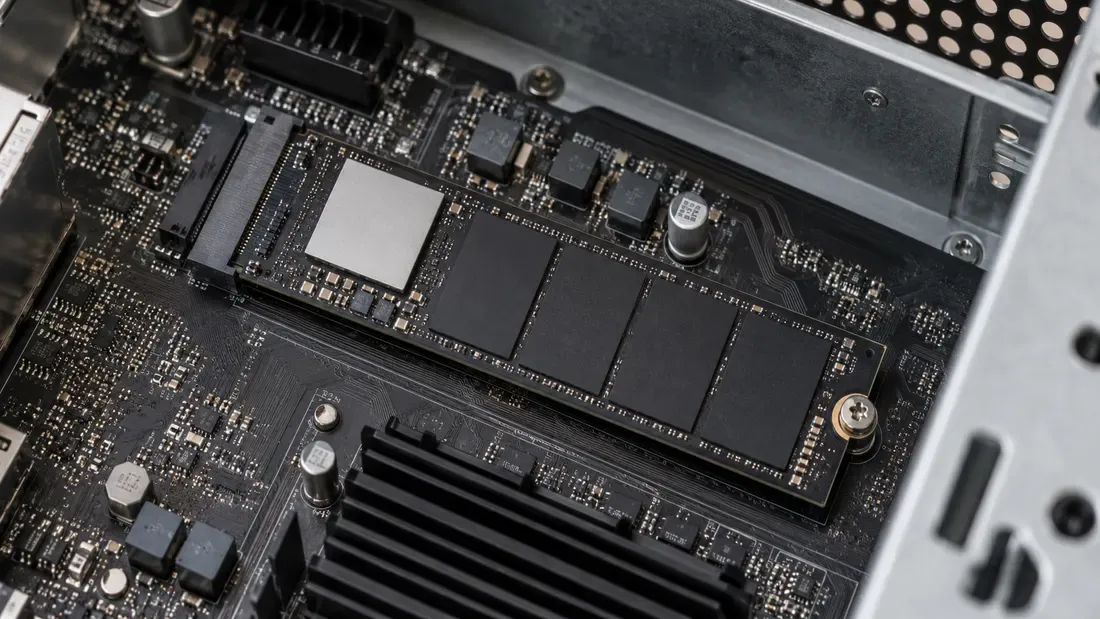
An NVMe SSD can fit a slot and identify correctly while its PCIe link runs at fewer lanes or a lower transfer rate than expected. First establish what the exact drive, slot and upstream port support, then measure the negotiated state. A socket shape alone does not promise x4 or a particular PCIe generation.
A lower negotiated link width or speed cannot be confirmed through generic throughput benchmarks, nor does it immediately indicate a defective SSD. Possible causes include the board layout, adapter, firmware settings, power policy or a hardware fault. A controlled comparison can narrow the cause without assuming that the SSD is defective.
For the distinct question of protocol and physical fit, see the M.2 SATA versus NVMe guide.
Distinguishing Link Width, Transfer Rate, and Protocol
PCIe link negotiation establishes two independent parameters:
- Link Width: The number of parallel differential physical lanes actively bonded (e.g., x1, x2, x4, x8).
- Transfer Generation/Speed: The signaling rate per lane, expressed in Gigatransfers per second (GT/s) (e.g., PCIe 3.0 at 8.0 GT/s, PCIe 4.0 at 16.0 GT/s, PCIe 5.0 at 32.0 GT/s).
Do not confuse these metrics with interface protocol. While an M.2 socket can mechanically support both SATA and PCIe wiring on certain motherboards, an M.2 SATA module uses the SATA interface; an NVMe SSD uses PCIe. An NVMe SSD showing x1 has not switched to SATA.
Record capability and negotiated status
To isolate the failure domain, map each boundary layer across the hardware topology:
| Diagnostic Domain | Parameter Evaluated | Baseline Capability | Active Negotiated Status | Verification Method |
|---|---|---|---|---|
| SSD Endpoint | Controller PCIe PHY | Reported endpoint capability (LnkCap) | Observed endpoint state (LnkSta) | PCIe configuration space inspection |
| Upstream Root Port / Switch | Root Complex / Downstream Port | Maximum supported port width/generation | Current negotiated downstream width/speed | Root Port Link Status register query |
| Board Slot / Interposer | Slot or adapter electrical routing | Documented lane routing and slot limits | Which slot and adapter were used | Exact board and adapter manuals |
| Platform Population | Lane sharing & multiplexers | Dedicated vs shared PCIe lanes (M.2/SATA/Slot sharing) | Actual slot population and any documented interaction | Exact platform manual |
| Firmware / UEFI | Slot bifurcation & link target speed | Relevant speed or bifurcation settings, if exposed | Recorded setting and measured state | OEM BIOS menu verification |
| Controlled Swap Validation | A/B testing on golden reference system | Known-good compatible slot and drive | Cross-swapped link width and speed metrics | Sequential unit isolation |
Interrogating the PCIe Bus in Linux and Windows
Linux Link Inspection
On Linux platforms, use lspci from pciutils to inspect the topology:
- Topology Mapping: Execute
lspci -tto visualize the bus hierarchy. Identify its upstream port and any intervening bridge or switch; confirm physical slot mapping in the board manual. - Capability vs Status: Run
lspci -vvand inspect the intended device by its bus/device/function address; privileged access may be needed for complete output.- Locate the Capabilities: [Express] block.
- Inspect LnkCap (Link Capabilities): Shows reported endpoint or port capability, not how many lanes the particular slot physically wires.
- Inspect LnkSta (Link Status): Indicates the currently negotiated link width and speed.
- Check the upstream root port's
LnkCapandLnkSta. If the reported capabilities exceed the negotiated state, investigate the actual board wiring, intervening components, platform settings and power policy. The mismatch alone does not identify a failed component.
Dynamic Link Rate Management and Load Verification
Microsoft documents NVMe Dynamic Link Rate Management for specific supported Windows, firmware and driver combinations. On such a platform, an idle link speed can be intentionally lower than under load. Do not assume every system has this feature.
Record link width and speed at idle and during representative I/O if the platform exposes both. Microsoft defines link status fields as negotiated width and speed; accessing them requires a suitable diagnostic interface. Keep the test workload and host power settings with the record. A low speed that persists under load still needs comparison with the board manual.
Host Multiplexing, Trace Routing, and Safe Swaps
If the link width remains locked at x1 under load:
- Consult Motherboard Trace Routing: Review the exact board manual. Check the slot wiring, adapter requirements and any documented lane-sharing rules. Do not transfer another board model’s population rule to this one.
- UEFI/BIOS Configuration: Check relevant link-speed or bifurcation settings only if the board actually exposes them. Always follow OEM engineering-approved change control procedures when modifying firmware settings.
- Controlled Isolation Swap: Power down the platform completely and follow the platform service instructions before performing physical hardware swaps.
- Move the suspect drive to a known-good compatible slot or test host.
- Install a known-good reference NVMe drive into the target production slot.
- Compare both drives in both positions if safe and compatible. If the issue follows one drive, investigate that drive and its seating; if it stays with one slot, investigate the slot, adapter and board configuration. Either pattern narrows the investigation but does not prove a single physical cause.
Send the recorded matrix and exact host/drive part numbers with a quote request so a candidate can be checked against the intended configuration.
References
We publish measured usable capacity and define trial-batch verification against the quoted product and agreed test scope.