
eMMC, UFS or microSD: embedded interfaces and host compatibility
- SD and eMMC/UFS are managed NAND, but use different interfaces and standards.
- The board and SoC constrain the options before price and capacity comparisons.
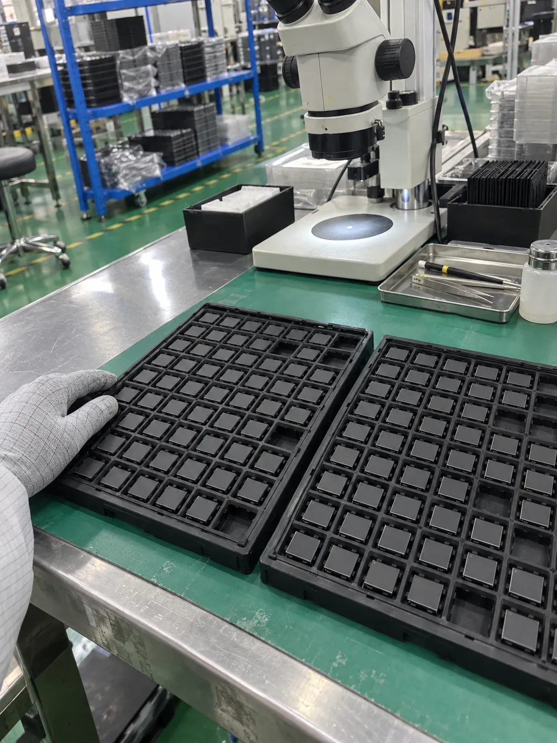
AI-generated scene illustration; not a factory photograph or evidence of testing.
eMMC, UFS and microSD are not interchangeable choices based only on capacity and price. The SoC, board design and boot mechanism determine the available interfaces; performance, power, package, endurance and serviceability distinguish candidates within that boundary. Replacing a part on an existing board differs from choosing the architecture for a new design.
An unavailable part number or growing log volume cannot be solved by buying another BGA device of the same capacity. BGA describes a package connection style, not interface, ball assignment or functional compatibility.
What the three technologies share
All three are managed NAND storage: NAND plus a controller that handles functions such as error correction, bad-block management and wear management behind a host interface. They do not follow a single standards family. SD/microSD follows SD Association specifications; eMMC and UFS follow JEDEC specifications. Raw NAND in a BGA package is a different option that requires appropriate external management; BGA alone does not identify managed storage. SD specifications and JEDEC flash-storage standards.
Removable card and soldered package have different service boundaries
| Storage | Typical integration | First compatibility checks |
|---|---|---|
| eMMC | Soldered board-level package | SoC support, ball map, voltage, boot partitions and supported functions |
| UFS | Soldered board-level package | Host and software-supported revision, serial connection, power and board design |
| microSD | Card and socket | SD host, capacity/filesystem, removal policy and installed contact stability |
A removable card permits replacement without board rework but introduces a socket, retention mechanism and accessible media. Check contact stability, maintenance and how the device handles removal. A soldered package removes that socket, not all mechanical risks: package, solder joints and PCB still experience stress.
Soldering also does not make data tamper-proof. A specialist can remove a package; confidentiality requires a system-level security design, including appropriate encryption and key/access management. Some equipment uses soldered system storage and a removable card for user data. That architecture still requires independent validation of both paths.
eMMC and UFS have different interface architectures
eMMC provides a parallel data bus, commonly configured for eight data bits, with data transfer in one direction at a time. UFS uses a serial link with separate transmit and receive paths and a queued command architecture. These distinctions help explain potential concurrency and performance, but neither architecture guarantees a particular application's speed.
Samsung's historical eMMC-to-UFS explanation illustrates this architecture change. Its older device comparisons are not current specifications for every eMMC or UFS part. In particular, eMMC 5.1 host/device implementations can support command queuing; do not generalize an older nonqueued eMMC comparison to all implementations. Consult the selected revision and both datasheets. See an implementation example in AMD eMMC 5.1 features.
Changing an eMMC package for a similarly sized UFS package is not an interface upgrade. The SoC controller, electrical design, board routing, power sequencing and software must support the new interface. A removable UFS-card specification also does not make that card a drop-in SD replacement.
Peak throughput depends on revision, negotiated modes, NAND, controller, capacity, temperature and workload. Avoid presenting one supplier's sequential numbers as standard-wide minimums. Similarly, eMMC is not automatically lower-power or cheaper for every purchasing situation: compare exact candidates and the complete system's active and idle behavior.
Existing-board replacement starts with full part identity
Collect present and candidate part numbers, datasheet revisions, dimensions, ball maps, voltage rails and required functions. The customer's engineering or maintenance team should identify the boot partitions, security features and management commands actually used.
Basic reads and writes do not establish successful boot, updating or abnormal recovery. Use a difference table with confirmed fields, customer-validation items and missing information before ordering samples. Delivery of a sample is not completion of qualification. For an existing design, use the second-source review for the deeper comparison.
A new design needs a workload and capacity budget
List startup files, AI models, logs, pictures, video, caches and update packages separately, with size, frequency and retention. A mostly read-only model library differs from continuously rewritten logs. Include filesystem allocation, reserved capacity and space required by the customer's update and rollback design; dual partitions and snapshots are examples, not requirements for every device.
Measure active and idle power with the intended workload. A peak-current figure alone is not an energy budget. Also confirm environmental limits, endurance evidence and any required configuration/change-control agreement; these are model-level requirements, not automatic properties of all embedded storage.
Validation must cover startup and updating
Plan sample checks around initialization, repeated boot, actual reads/writes, near-full behavior and the customer's update and recovery workflow. For abnormal power interruption, use dedicated authorized samples with expendable data and predefined acceptance criteria. A successful reboot alone does not prove every file intact or drive-level PLP.
Record the storage lot and full part number alongside host hardware, firmware, workload, conditions, errors and results. The statement eMMC passed is insufficient. Vibration checks should address the installed system even without a removable card socket.
Kalstor supplies hardware. Drivers, Bootloader, software updating, installation and recovery implementation belong to the customer or its designated provider.
Send requirements that can identify a candidate
Provide SoC or motherboard model, current part number, desired interface/capacity, package requirements, environment, workload and expected quantity. Distinguish a new architecture from a replacement: an architectural suggestion is not a drop-in guarantee.
Review embedded storage options and submit the hardware requirements. Availability, confirmable configuration and customer-validation items need a model-level reply. The catalog-to-lot guide explains why a family name is not a complete order specification.
FAQ
Is UFS always more suitable than eMMC?
Does soldered storage eliminate vibration testing?
Does BGA mean eMMC?
References
We publish measured usable capacity and define trial-batch verification against the quoted product and agreed test scope.