
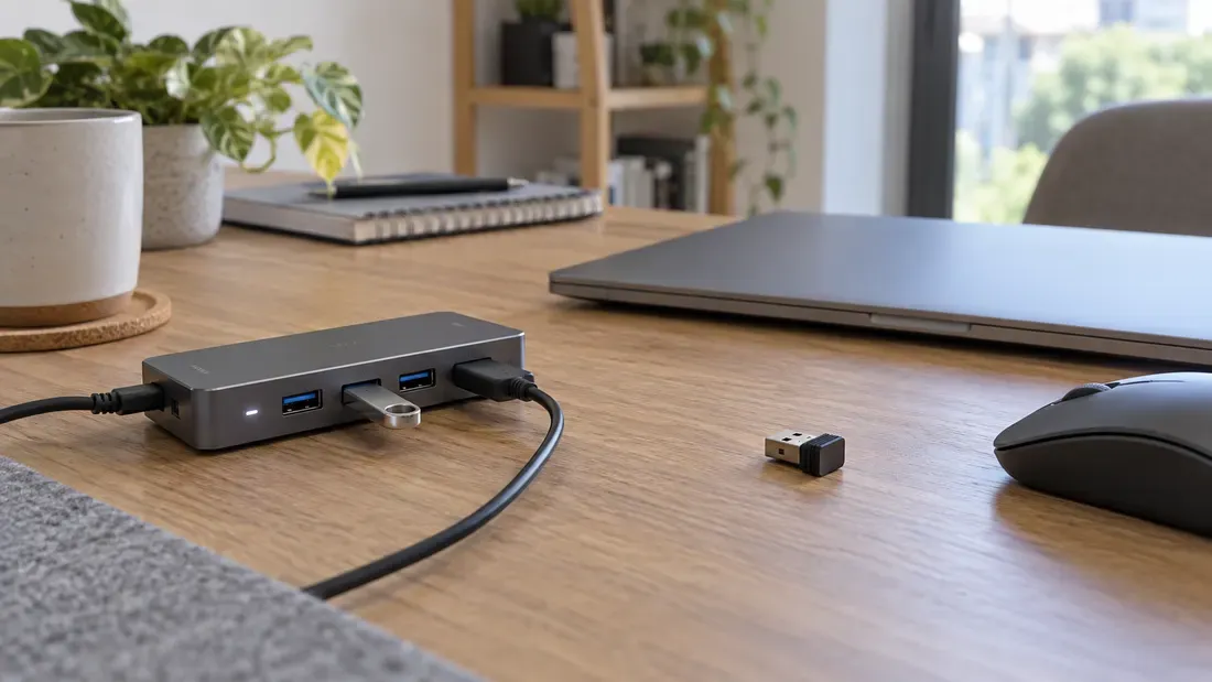
USB 3.x Differential Signaling and 2.4 GHz RF Interference Diagnosis
- Some SuperSpeed USB arrangements can reduce sensitivity of nearby 2.4 GHz receivers.
- Isolating RF degradation requires distinguishing wireless receiver desense (RSSI/packet loss) from host controller USB link-layer errors.
- Compare receiver position, approved cable/port layouts and wireless band where supported.
The USB 3.0 interference white paper documents cases where noise from a SuperSpeed USB link reduces the sensitivity of a nearby 2.4 GHz receiver. A wireless problem that appears when a USB storage device is connected is therefore worth a controlled layout test. It does not prove that the flash memory or even the USB assembly is defective.
Separate radio loss from USB failure
Before changing hardware, capture both sides of the incident. On the wireless side, record the radio band/channel, receiver location, traffic rate, retries or packet loss, and signal readings if available. On USB, record whether the storage device stays enumerated, its negotiated link mode, copy result and host reset or disconnect events. A radio dropout with stable USB transfer suggests a different investigation from a USB disconnect with a healthy radio.
Use the same layout for each comparison
| Condition | Keep constant | Observe |
|---|---|---|
| Baseline, USB device absent | Wireless channel, peer and application load | Wireless error rate and signal reading |
| Device connected, idle | Same receiver location and radio traffic | Whether the symptom appears without USB transfer |
| Representative USB transfer | Same cable, port and radio traffic | Wireless result and USB link/log result |
| Receiver moved away | Same USB transfer and radio setup | Whether distance changes the symptom |
| Alternative approved cable or port | Same positions where practical | Whether the result follows cable/port layout |
If supported, a separate 5 GHz wireless comparison can help identify a 2.4 GHz-specific problem; it does not identify the exact radiating component. Other local radio interference and antenna design still need consideration.
Decide what to change
Where the comparison is repeatable, test receiver placement or a cable and enclosure configuration approved for the product. The white paper's example setup is not a universal distance or shielding specification. Record the final physical configuration and retest the actual wireless application and USB workload. Include the device, port and antenna layout with a quote request if selecting storage for the design.
We publish measured usable capacity and define trial-batch verification against the quoted product and agreed test scope.