
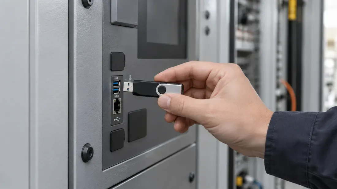
Qualifying USB Maintenance Drive Connector Wear in Field Service
- The USB Type-C specification defines a 10,000-cycle durability test for connector families under laboratory conditions, but this metric cannot be applied as a blanket rating for finished drives or legacy USB-A hardware.
- Comprehensive field qualification requires evaluating the entire mated system while isolating drive plug degradation from host receptacle wear.
- Engineering teams must pair mechanical and visual wear evaluations with strict protocol enumeration and data integrity verification.
Durability Realities in Field Service Environments
USB flash drives deployed for field engineering—such as firmware patching, system recovery, diagnostic logging, and offline system imaging—may be connected to many host ports during a service program. The mating duty cycle should therefore be recorded for the actual use case.
The USB Type-C Cable and Connector Specification defines a durability rating of 10,000 insertion and extraction cycles for specific connector families subjected to standardized test procedures. However, this specification applies strictly to standardized laboratory test conditions of connector components. It does not certify that any fully assembled commercial drive, custom ruggedized enclosure, or legacy USB Type-A connector will withstand equivalent mechanical cycling. Engineers cannot assume a universal cycle quota across different form factors or manufacturing runs.
Distinguishing Plug Wear from Receptacle Wear
A complete qualification program evaluates the mated pair—the male drive plug and the female host receptacle—to ensure neither damages the other prematurely:
- Drive Plug Wear: Inspect the plug contacts and shell for wear or deformation after the defined cycle test.
- Host Receptacle Wear: Field test fixtures must isolate whether interface failures stem from worn drive contacts or from worn female ports on field equipment. Compare a reference drive in the suspect receptacle and the candidate drive in a reference receptacle to narrow the fault location.
Step-by-Step Qualification Matrix
To establish valid operational limits for service drives, qualify the specific connector vendor design and housing assembly using the following framework:
| Qualification Phase | Evaluation Focus | Acceptance Criteria |
|---|---|---|
| 1. Baseline Assessment | Initial mechanical fit and electrical baseline. | Record the exact plug and receptacle specifications and a baseline enumeration and verified transfer. |
| 2. Prescribed Cycling | Controlled mating cycles matching the target deployment duty cycle. | Record cycle count, mating counterpart, orientation and any off-axis events. |
| 3. Mechanical & Visual | Contact finish inspection and shell retention analysis. | Apply acceptance criteria from the exact connector specification and service requirements. |
| 4. Enumeration Integrity | Host controller communication and handshake consistency. | Record detection time, disconnects and host logs on defined reference ports. |
| 5. Transfer & Log Verification | Sustained I/O payload validation and error monitoring. | Verify a known payload after cycling and record any resets, disconnects or errors; set pass limits before testing. |
Lifecycle Verification for Fleet Deployments
Evaluate the assembled drive with its intended mating port. The Type-C component test is a comparison point only; it is not a field-life prediction for another connector or complete product.
Include the connector type, target cycle duty and host ports in a quote request.
We publish measured usable capacity and define trial-batch verification against the quoted product and agreed test scope.