
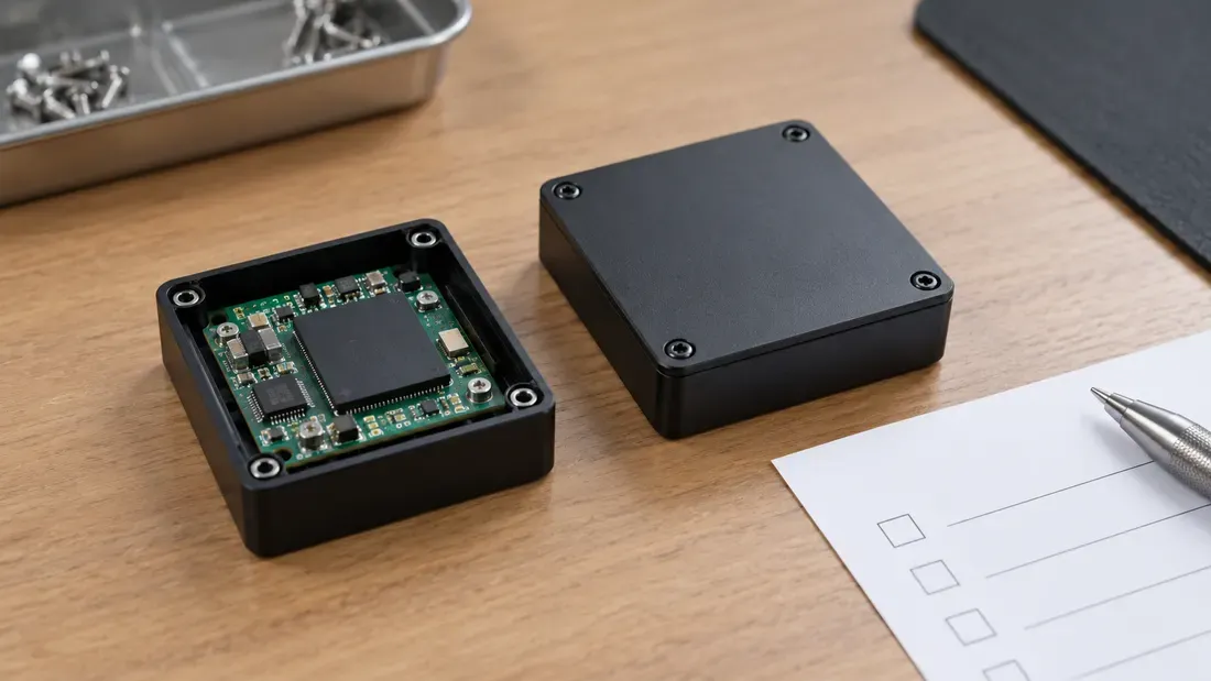
Troubleshooting UDP USB Disconnection After Enclosure Assembly
- Compare assembly stages without assuming mechanical stress or flash-controller failure by testing the identical unit before and after enclosure integration under identical host conditions.
- Audit connector alignment, mounting torque, and internal clearance against the official supplier mechanical drawing before assuming solder or component defects.
- Capture kernel enumeration logs systematically across incremental assembly steps without live probing or ad hoc wiring.
A board-level UDP or COB USB module that works on an open bench but fails after enclosure assembly presents an assembly-state correlation. It does not identify solder, controller silicon or the molded package as the cause. The useful test is the same physical unit across controlled assembly stages.
Freeze the electrical baseline
Record module part and revision, host port, board revision, firmware, USB cable/path, power configuration and workload. Capture USB enumeration and I/O error logs while the assembly is open. Repeat the same workload after each approved mechanical step; avoid live probing, makeshift wires or bending the board to reproduce a symptom.
Inspect the assembly boundary
| Stage | Mechanical observation | Electrical/USB observation |
|---|---|---|
| Open board | Module seating, connector alignment and board support | Identity, enumeration, representative verified transfer |
| Lower housing installed | Clearance to module and board, standoff contact | Same USB identity and error log |
| Fasteners installed | Order and torque from the exact drawing, visible bow or contact | First step at which failure appears |
| Cover closed | Pressure points, cable strain, connector alignment | Repeated transfer and disconnect record |
A supplier package drawing describes the module, while the product's enclosure drawing and work instruction define mounting and fastener limits. If those documents are unavailable, record the gap before production qualification. Do not assume a generic UDP dimension, torque or insertion depth.
Narrow the cause without guessing
If the failure follows a particular closure step, compare a known-good assembled unit or a permitted mechanical revision while holding software and host constant. If it persists on the open board, investigate the electrical path separately. Preserve the failing unit and assembly record for engineering review; disassembly can remove the evidence. The supplier customization example shows that module geometry can be design-specific, not that Kalstor provides a particular custom assembly. Include the exact drawings and failure stage in a quote request.
We publish measured usable capacity and define trial-batch verification against the quoted product and agreed test scope.