
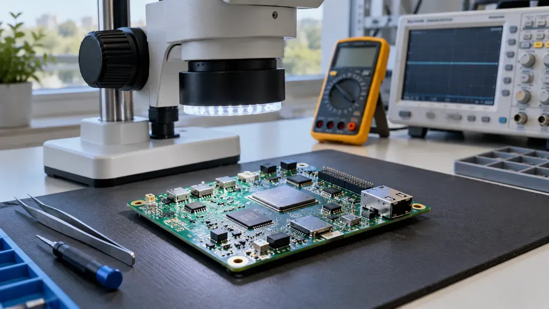
eMMC Not Detected on New PCBA: Root Cause Evidence Matrix
- Isolate power rails, signal integrity, host driver stack, and physical assembly instead of presuming solder bridging or voids.
- Use designated test points for rail and clock verification; avoid hazardous live probing under the BGA package.
- Use applicable BGA guidance and controlled comparisons to narrow, not presume, the cause.
An eMMC missing on a newly assembled board is an observation, not a solder diagnosis. Keep the first failing unit and its logs intact until the failure stage is understood. Rework or repeated assembly can erase useful evidence. Compare with a known-good board of the same revision before blaming the memory component.
Capture evidence by failure layer
| Layer | Record | What a difference may narrow |
|---|---|---|
| Identity and assembly | Exact eMMC marking/part, placement, PCB and assembly lot | Wrong or rotated part, revision mismatch |
| Board power — check first | VCC and VCCQ against the exact eMMC specification: steady values with a multimeter, startup droop/transients and ripple with an oscilloscope at approved test points | Supply distribution, regulator, decoupling or sequencing path |
| Host communication | Clock/reset/command observations through safe, designed access, plus boot logs | Whether the host attempted initialization and received a response |
| Software | Boot ROM/BSP revision, pinmux and driver messages | Configuration or host-support path |
| Physical inspection | Manufacturer drawing, factory inspection record and X-ray if suitable | Visible assembly anomaly for qualified review |
Only trained hardware personnel should take powered measurements using board-designated points. Do not improvise flying wires, probe under a BGA package or touch storage contacts in operation. The Micron BGA guide is an example of package handling guidance, not evidence that a given board failed soldering.
Start with board power before interpreting missing eMMC responses. Measure steady VCC/VCCQ with a multimeter, then use a suitably rated oscilloscope to capture initialization-time voltage sag and ripple at designated test points; a multimeter reading alone may miss a short startup event. If a rail is out of specification, check the LDO or DC-DC converter output, missing or incorrectly valued decoupling capacitors, and the approved PCB layout for excessive trace resistance or voltage drop. Compare against the schematic and a known-good board before replacing the memory package.
Narrow the fault domain
Keep host firmware and power conditions constant during controlled comparisons. If the missing device follows a board, investigate board assembly, supply and software together; if it follows a part after an approved swap, investigate part identity and handling. Neither outcome alone proves one root cause. Preserve the failing sample and do destructive rework only under the manufacturing investigation plan. Share part, board, boot-log and inspection evidence in a quote request when qualifying a replacement.
References
We publish measured usable capacity and define trial-batch verification against the quoted product and agreed test scope.